
- Electromagnetic Deflection Tube / EM Deflection Tube. X 1 unit
- Universal EM Tube Holder. X 1 unit
- Extra High Tension Power Supply / EHT Power Supply. a.k.a Extra High Voltage Power Supply / EHV Power Supply. X 2 unit
- Fix or Variable 0 V - 12 V 5 Amp Power Supply. X 1 unit
- Helmholtz Coils. X 1 pair
- Rheostat 11 Ohm 3.3 Amp or Decade Resistance Box. X 1 unit
- Digital multimeter. X 1 unit
Electromagnetic Deflection Tube / EM Deflection Tube / Teltron Deflection Tube setup diagram.

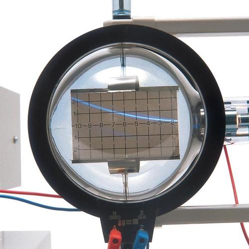

The beam from the deflection tube is produced by a horizontal slit in the anode. So the beam fans out to produce a ‘V’ of electrons in the horizontal plane. This is aimed at a vertical fluorescent screen inside the tube. The vertical screen is at an angle to the beam direction. So the fan of electrons cuts across the screen, producing a straight line along it. The path of the electrons shows up blue because there is a residual amount of hydrogen gas in the tube. If The paths of the electron beams are green, because the electrons are travelling through a residual amount of helium gas. The deflection plates are positioned above and below the screen, which has its own graduated scale. So the effect of the deflecting voltage can be measured on the scale. Using the graticule, it is possible to show that the path is parabolic in an electric field and circular in a magnetic field.
Caution.
The apparatus uses high potential which can cause serious injury and even death, please exercise care when handling the apparatus. Ask if Doubt.
Source:
Types of electron tube by Practical Physics.Org
Buy DIRECT from 3B Scientific